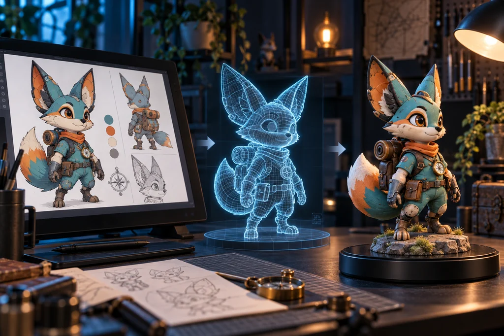
An image-to-3D service can produce a rotatable character in minutes. That does not make it printable. The model may invent the unseen back, leave holes inside ears, overlap clothing and accessories, or reduce thin straps to geometry that disappears in the slicer.
This guide was checked against official Meshy, Blender and Prusa documentation on September 10, 2026. It organizes the work as image → multi-view reference → 3D generation → mesh repair → part separation → slicing → test print. The goal is not a one-click recipe for one vendor, but a set of pass criteria that transfers between tools.
The pipeline and its gates
| Stage | Deliverable | Pass condition | Common failure |
|---|---|---|---|
| Design | Multi-view sheet | Silhouette and details agree | AI invents the back |
| Generation | Source mesh | Major shape is correct | Holes and fused parts |
| Repair | Print mesh | Closed surface and safe thickness | Thin parts vanish |
| Split | Assembly parts | Keys fit and parts are reachable | Supports cannot be removed |
| Slice | Printer job | No islands or weak starts | Bad orientation |
| Test figure | Surface, fit and balance pass | Final-size failure |
1. Build a reference sheet for reconstruction, not applause
A frontal illustration contains no evidence for the back of the head, the rear of a backpack or the tail joint. A single-image model estimates those regions. Meshy's documentation similarly notes that partial views can create missing parts and recommends multi-view inputs when fidelity across front, side, back and three-quarter views matters.
Write down the immutable traits first. Our original character locks a teal jacket, orange scarf, cream muzzle, compass pendant and cylindrical pack. Use a neutral pose, similar camera height, soft light and a plain background across every view. Compare the number and location of every prop. Dramatic perspective may look impressive, but it changes apparent lengths and is poor reconstruction evidence.
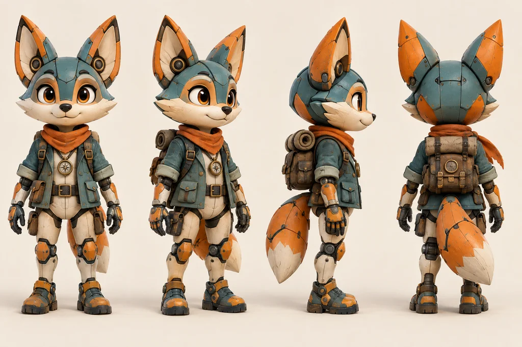
Reference-sheet prompt
~~~text Create a production reference sheet for one original teal-and-orange mechanical fox explorer. Lock the large ears, cream muzzle, teal field jacket, orange scarf, compass pendant and cylindrical backpack. Arrange full-body front, three-quarter, side and back views in the same neutral pose and proportions. Use near-orthographic cameras, even soft light, a pale plain background and clear silhouettes. Keep colors, accessories, placement and counts identical in every view. Exclude text, logos, watermarks, cropped anatomy and dramatic perspective. ~~~
2. Choose shape before texture
Generate several candidates and compare the large forms before committing. Check face width, ear thickness, separation between limbs, space around the tail, and contact between feet and base. A beautiful texture cannot rescue an expensive silhouette error.
Meshy currently offers image-based generation, multi-view workflows, remeshing and export. Its official method guide positions a single image as a clear visual target and multi-view input as the higher-fidelity route when several angles exist. Product names will change, so record the input views, topology mode, polygon target and export format. Keep the untouched source generation for later repair.
3. Decide size and printing process first
The same detail behaves differently on a 150 mm resin statue and a 70 mm FDM miniature. Resin favors small facial and surface detail but introduces washing, curing and material-safety steps. FDM is accessible for larger bases and prototypes, while tiny features may merge or disappear depending on nozzle and layer settings.
Set final height, process, material and printer profile before choosing wall thickness. Prusa's modeling guide uses a 0.4 mm nozzle and roughly 0.45 mm extrusion width as an example of why a wall thinner than one perimeter may not print. It is an example, not a universal minimum. Slice with the actual profile and confirm that every feature remains in layer preview.
4. Repair the AI mesh into a printable solid
Typical defects include open ear cavities, flipped normals, intersecting clothes, zero-area faces and fragile straps. Blender's 3D Print Toolbox checks non-manifold and bad-contiguous edges, intersections, degenerate or distorted geometry, thickness, sharp edges and overhangs. Make Manifold is a starting aid, not proof of printability. Re-run the checks and compare the silhouette after every repair.
Thicken or connect vulnerable hair tips, ears, fingers and antennae. Merge floating decoration. Separate a tail, backpack or other parts where supports would be trapped. Add asymmetric keys so assembly direction is obvious, then test clearance with a small coupon; tolerances vary by machine and material.
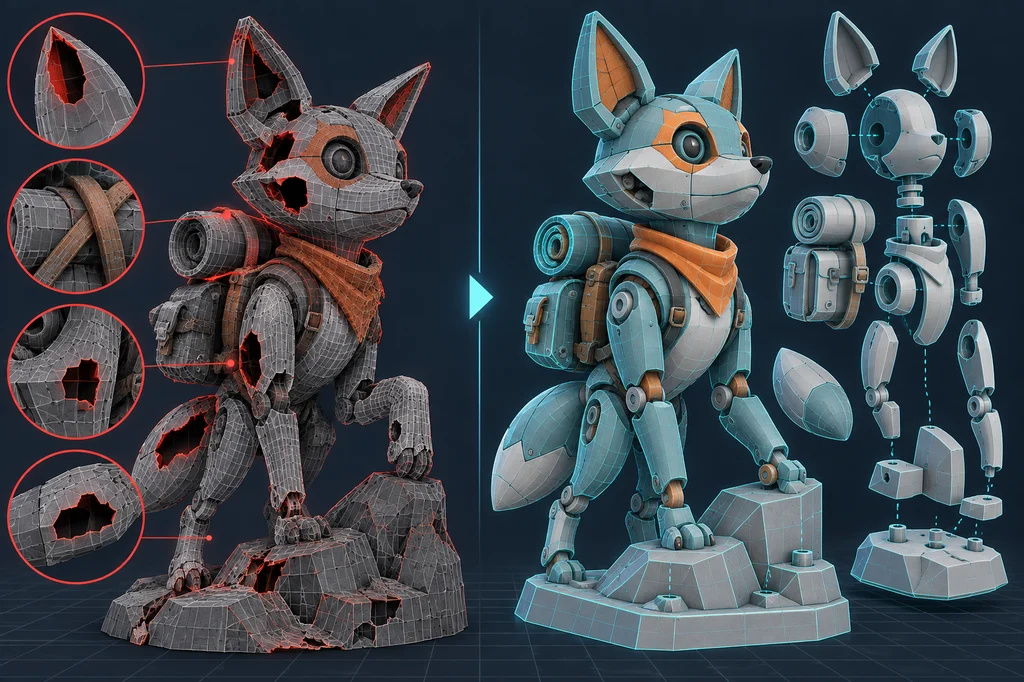
Mesh-repair visualization prompt
~~~text Create a technical before-and-after visualization of the same mechanical fox 3D model. On the left, reveal holes in ears, intersecting backpack straps, thin walls and messy topology with restrained red diagnostics. On the right, show a watertight surface, safe thickness, clean topology, separated parts and keyed joints in cyan. Use a professional dark 3D workshop, legible wireframe and solid shading. Exclude identifiable software UI, readable text, logos and watermarks. ~~~
5. Orientation and supports design the visible surface
Automatic supports can place scars on the face or chest. Rank the visible surfaces first, then move contact points toward the back of the head, rear of the body and underside of the base.
Prusa explains that orientation is crucial in (M)SLA printing. Tilting a broad surface can reduce peel-force concentration and distribute supports, but “always 45 degrees” is not a rule. Step through the sliced layers: avoid unsupported islands, abrupt jumps in cross-sectional area and weak first contacts.
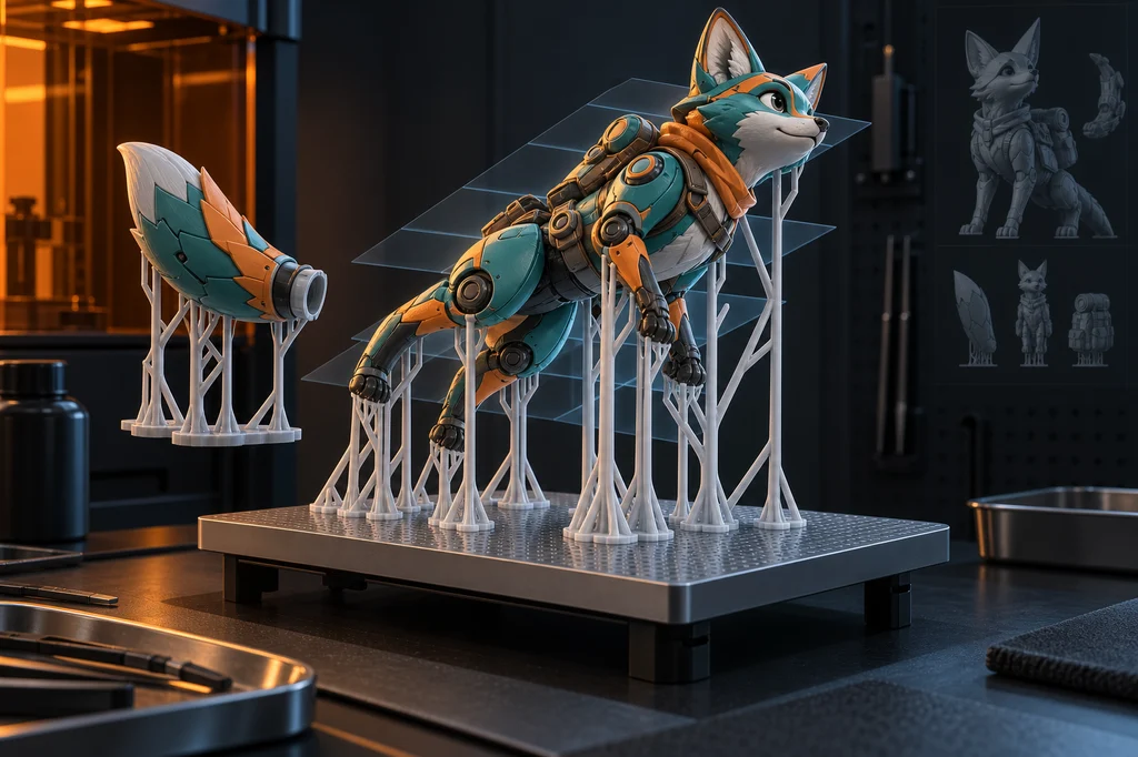
Orientation-and-support prompt
~~~text Visualize resin-print preparation for the same teal-and-orange mechanical fox figure. Tilt the model over a rectangular build plate and attach tree supports mainly to hidden surfaces. Place the tail and backpack nearby as keyed assembly parts and show subtle translucent slice layers. Use believable engineering geometry, precise contacts and cyan-orange workshop light. Exclude readable interface text, logos, watermarks and impossible floating pieces. ~~~
6. Make failure cheap with targeted tests
The first test does not have to be a small complete statue. Cut coupons containing the face, ear tip, hand, tail joint and assembly key at final scale. They reveal thickness, surface quality and fit with little material. Follow with a draft whole-body print for balance and assembly, then use the final quality profile.
Record support scars, delamination, warping, joint error and stability with photos and measurements. For resin, follow the material and printer manufacturer's current PPE, ventilation, washing and curing directions. Prime the cleaned model before painting; an even coat makes seams and surface defects easier to see.
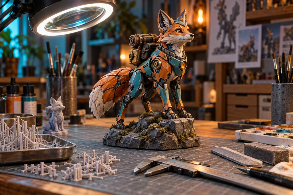
Finished-figure inspection prompt
~~~text Show the completed teal-and-orange mechanical fox 3D-printed figure under inspection in an artisan workshop. Place the painted figure on a rocky base beside one gray test print, removed supports, calipers, sanding tools and brushes. Render believable resin detail, clean seams, stable balance and premium product lighting. Exclude readable text, brand logos and watermarks. ~~~
Final checklist
- The character is original or every reference is licensed for this use.
- Front, side and back silhouettes and accessory positions agree.
- Thin ears, straps and fingers survive the real slicer profile.
- The mesh is closed and free of flipped faces, intersections and degenerate elements.
- Separate parts have unambiguous keys and tested clearance.
- Support contacts avoid the most important visible surfaces.
- Risk-part coupon, full draft and final print are validated in that order.
AI 3D generation does not remove modeling. It shortens the distance from an idea to an editable volume. Reliable physical results come from consistent views, print-aware repair, layer-by-layer inspection and small tests—not from the generation button alone.
Verified official references
- Meshy quick start and post-processing
- Meshy Image to 3D and multi-view
- Meshy generation-method guide
- Blender 3D Print Toolbox
- PrusaSlicer object orientation
- Modeling with 3D printing in mind
Models, formats and printer profiles change. Check the current service documentation, manufacturer instructions, material safety data and terms before production.